 Rain Gages
In June of 1980, the Urban Drainage and Flood Control District, in cooperation with the cities of Lakewood and Wheat Ridge, Jefferson County and The Consolidated Mutual Water Company, began a program to develop an early flood detection network and flood warning plan for Lena Gulch. The Lena Gulch basin, located in central Jefferson County, drains approximately 13.8 square miles at its confluence with Clear Creek near Kipling Street. The Lena Gulch headwaters are located in the Apex Gulch area of Lookout Mountain. Apex Gulch and Jackson Gulch join to form Lena Gulch just below Heritage Square near the intersection of U.S. Highway 40 and State Highway 93. Numerous developed areas downstream from this point are considered highly flood prone. Lena Gulch flooding will impact numerous major highways and arterial streets in addition to the developed areas within unincorporated Jefferson County and the cities of Lakewood and Wheat Ridge.
One major water supply reservoir (Maple Grove Reservoir), which is owned and operated by The Consolidated Mutual Water Company, provided further impetus for implementing the $100,000 Lena Gulch flood warning plan and early detection network. The dam and reservoir, located near West 27th Avenue and Youngfield Street, performs an important flood control function for storm runoff events through the 100-year flood. Improvements to the dam and spillway were completed in 1977 to comply with the dam safety requirements of the State Engineer. These improvements included the installation of two Fabridams on the spillway crest which are operated in a manner to protect the dam from failure in the event of floods exceeding the 100-year magnitude. UDFCD participated in the construction of one of these Fabridams as part of a major channel improvement project for Lena Gulch through the City of Wheat Ridge. The downstream flood control improvements, totaling more than $5,000,000 in construction costs, rely heavily on the flood control benefit provided by Maple Grove Reservoir. Should Fabridam deflation be required in a severe emergency, discharges well in excess of downstream channel capacity can be expected with the loss-of-life potential being extremely high. In consideration of the numerous problem areas within the Lena Gulch floodplain and the special warning needs with respect to Maple Grove Reservoir, an automated real-time detection network was selected by the project sponsors for implementation. The 1986 flood season represents the first full year operation of the Lena Gulch detection network which employs state-of-the-art microcomputer technology, real-time data collection, advanced meteorological forecasting and hydrologic modelling. The remainder of this article will deal primarily with the telemetry system and data processing components which comprise the "Lena Gulch Flood Detection Network." The reader should keep in mind that this real-time data collection system represents only one element of the overall "Flood Warning Plan" for Lena Gulch. Other elements, including meteorological support, communications, warning dissemination and emergency response should not be given lesser importance. Failure of any one or combinations of these elements could cause the entire warning plan to fail.
The flood detection network for Lena Gulch, modelled after a similar system for Boulder Creek, consists of six self-reporting rain gages, three automated steam gages and two base stations. All remote gages report data using standard formats (ASCII or binary) through battery powered VHF radio transmitters. The base stations receive radio signals from each gage, decode the transmitted data and process the data with the aid of a microcomputer. The following paragraphs provide a more detailed description of the telemetry equipment, remote sensors and base station features.
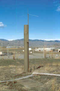
Rain GagesAll six self-supporting rain gages are standard tipping bucket gages. Each bucket tip represents 1.0 mm of rain or approximately 0.04 in. Each bucket tip trips a magnetic switch which causes the weather data transmitter to power up and transmit the Gage I.D. and an accumulator value of 0 to 99. Each bucket tip causes the accumulator value to increase by one. The tipping buckets are housed in the top section of a 12-inch diameter standpipe assembly, which stands approximately 10 feet above the ground surface. The weather data transmitter is housed in the lower portion of the standpipe assembly approximately 2 feet below the ground surface. A side mounted antenna mast supports an omni-directional antenna.
All three stream gage sensors are pressure transducers (PT.) capable of sensing minor changes in stream stage (less than 0.1 feet). The PIN are calibrated to measure a stream stage range of 0 to 15 feet. The calibration curve is linear and represents measurements in terms of volts (range 0 to 5 volts). The weather data transmitters are set to report stage in an event-time (ET) mode. This type of reporting is accomplished in the following manner:
Each PT is housed in a sealed 4 inch PVC pipe with end caps and can be mounted to almost any solid object. One end of the PVC housing contains a 1 /4 inch diameter orifice which allows fluids to reach the PT. Watertight flexible plastic tubing is attached to the other end of the PVC housing to protect the electronics portion of the PT and house the wire cable leading to the weather data transmitter. The flexible conduit connects to a vertical PVC sewer pipe which houses the transmitter approximately 2 feet below the ground surface. Antenna types and mountings are site dependent, varying from a short wire whip to an omni-directional antenna mounted on an aluminum chain link fence. Low profile installations were selected to help prevent vandalism.
The base stations consist of microcomputers operating database software with various display routines and multi-tasking capabilities. The data collection software is the ALERT package originally developed by the National Weather Service (ALERT "Automated Local Evaluation in Real Time"). Base station hardware includes; VHF radio receiver, weather data decoder, micro-computer, printer and backup power supply.
The primary base station is located at the offices of Henz Kelly and Associates (HKA), near 1-25 and Colorado Blvd. HKA is a private meteorological firm under contract to perform specific services for the District. The secondary or backup base station is located at the Jefferson County Office of Emergency Preparedness. A third base station (not part of the Lena Gulch system) is located at UDFCD offices to function as areawide support and provide for remote access by other authorized users such as the National Weather Service. Special features of the primary base station are outlined in the following paragraphs:
The preceding presents a general overview of the key components which make up the Lena Gulch Flood Detection Network. The total system design and costs, which total $100,000, include other items such as radio repeaters, antennas, a duplexer and maintenance related equipment. While the total system design may be considered as over-kill where Lena Gulch is concerned, this system was selected to allow future detection networks to be added on with minimal effort. A buy-in procedure has been proposed to pay back some of the costs borne by the sponsors of the Lena Gulch project. Future systems are currently being considered for Bear Creek, Clear Creek and for the Ralston/Van Bibber/Leyden Creek area affecting the City of Arvada.
The responsibility for monitoring the Lena Gulch Flood Detection Network currently falls upon the private meteorological firm of Henz Kelly & Associates (HKA). Procedures and decisions aids for disseminating flood forecasts are presented in a document entitled: LENA GULCH FLOOD WARNING PLAN. Timely flood warning for Lena Gulch relys heavily on early meteorological predictions. Various rainfall scenarios can be looked at using the hydrologic and routing procedures of the Lena Base Station well in advance of rainfall. During an actual storm event, real-time data can be observed, predictions adjusted, earlier notifications updated and decisions made with respect to appropriate emergency responses. The meteorological component, while not the emphasis of this article, should not be underestimated. In a real emergency, certain developed areas along Lena Gulch have less than 30 minutes to evacuate from the time of peak rainfall. Too heavy reliance on real-time data, in such areas, could prove disastrous. On the other hand, real-time data and proper interpretation should reduce the false alarm rate and increase confidence in effecting emergency operations, particularly for affected areas in the lower portion of the basin and below Maple Grove Reservoir.
The Lena Gulch Flood Warning Plan is a document which is updated annually and spells out the responsibilities of all parties involved with responding to a flood emergency. Critical elements of the plan include: 1) detection and evaluation; 2) dissemination of the warnings; and 3) warning response. All elements of the warning plan must function properly or the plan will fail. Standard operating procedures (SOPs) for the various response agencies are detailed in the document. Procedures are also described for disseminating warnings to the public, informing the news media of the potential flood hazard and conducting annual exercises.
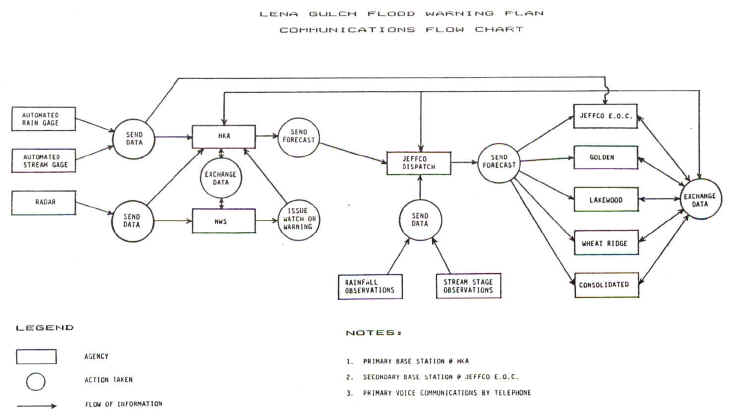
Communications is one aspect of the plan which needs special emphasis. The accompanying Flow Chart illustrates the complexity of the communications network for Lena Gulch. Dispatch operators are not well versed in the areas of meteorology and hydrology. Care must be taken to make certain that the correct communication occurs and critical messages are not delayed. Timely response to an emergency relies much more heavily on proper communications than the accessibility of real-time weather data.
Since the installation of the Lena Gulch Early Flood Detection Network, no emergency situation has developed nor for that matter has any significant rainfall event occurred. The inevitability of this project is that one day, the Lena Gulch Flood Warning Plan will be tested and a real emergency will develop. The success of this program will be evaluated at that time and the public will be the judge.